
At Euler Precision we want to capture the interest of potential clients by showing our technical capabilities and good practices. A good way we achieve this is through our business card, when we show up at fairs and conferences.
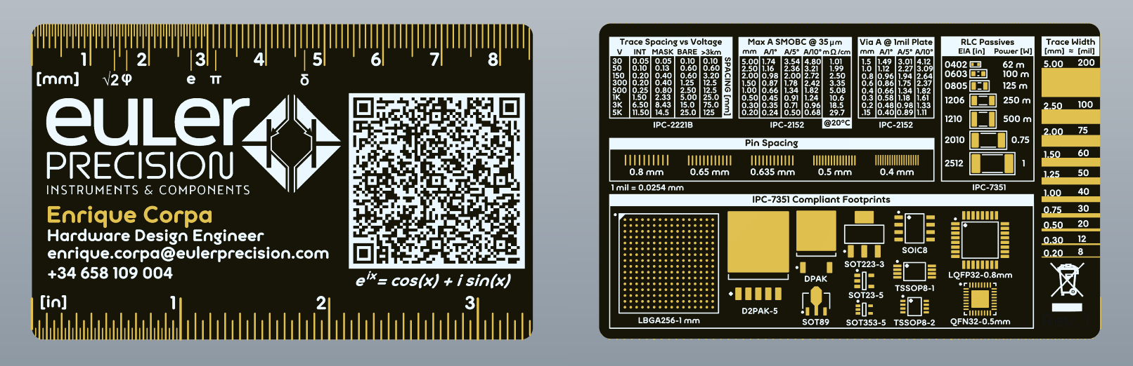
As we are technically inclined, we have designed a business card with the same technology that is used to manufacture printed circuit boards (PCBs). Matte black solder mask and gold-nickel metallization (ENIG) process gives our card the look of a high quality circuit board. The main substrate is made of standard FR4 TG 130-140 fiberglass with a thickness of 0.8 ± 0.1mm. The card also has a 35 micron thick copper layer top and bottom.
Below we describe the characteristics of the card:
 The ruler starts from the edge of the card, so it can be used to measure object’s dimensions by resting it on a surface next to that item. The first three centimeters have extra 0.5 mm divisions to increase the available resolution. The rest of the ruler’s divisions are 1 centimeter and 1 mm with a slightly longer mark to indicate half’s of a centimeter.
 The Euler Precision logo, showing part of a differential pair with PNP transistors.
 The QR code allows contact information to be added to any smartphone quickly and efficiently. Contains contact information in VCard 4 format. Information included in the card is:
 Another math reference: Euler’s formula, which relates the complex exponential with rotations in the complex plane.
 Just like the millimeter ruler, the ruler starts from the edge and has 25-thou marks (0.635 mm) along the first inch. From there, subsequent marks are one inch (1000 thou, 25.4 mm) and 100 thou (2.54 mm) with short marks to indicate 50 thousand (1.27 mm).
 The back of the card has some engineering references for the design of printed circuit boards. All component tables and footprints follow the IPC recommendations, and the specific standards for each table are shown below.
 This table shows the required spacing (clearance) according to the IPC-2222A table. The voltage at which an electric arc (corona) occurs between two conductors is determined, according to Paschen’s law, by the distance between them, the atmospheric pressure and the composition of the gas that surrounds them. The values in the IPC table are very conservative with respect to the usual dielectric breakdown of air, but it is highly recommended to follow them. As a side note, clearance is not the same as creepage.
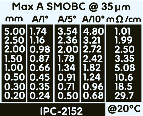 Maximum current for a single copper trace covered with solder mask (SMOBC: Solder Mask Over Bare Copper) as a function of width and allowed temperature rise (ΔT).
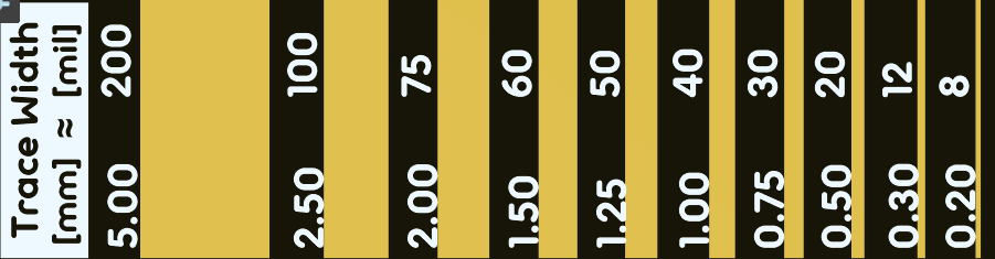
Most trace widths in the table match the trace samples shown in [12].
Maximum current for a single copper trace covered with solder mask (SMOBC: Solder Mask Over Bare Copper) as a function of width and allowed temperature rise (ΔT).
Most trace widths in the table match the trace samples shown in [12].
 Maximum current through a via as a function of its diameter and the allowed temperature rise(ΔT). A two-layer, 0.00254 mm (1 mil) metallized via is assumed. Values shown in the table are for the most common via diameters.
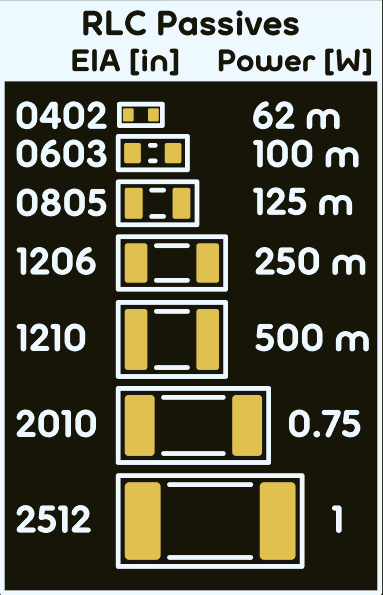 Samples of the most common SMD package sizes for passive components, indicating their size in imperial units with the EIA standard, since this is the most common nomenclature. Footprints follow IPC recommendations.
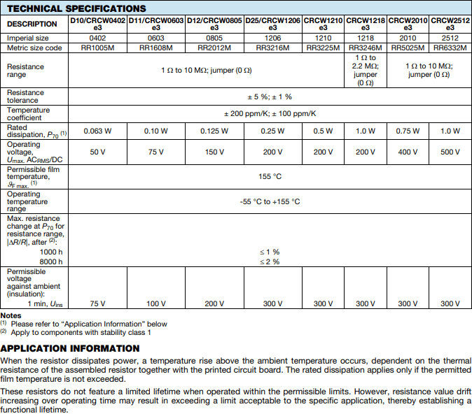
A maximum recommended power rating is also indicated in the case of resistors of these sizes, taking as reference the Vishay’s D/CRCW series (Standard Thick Film Chip Resistors).
Samples of the most common SMD package sizes for passive components, indicating their size in imperial units with the EIA standard, since this is the most common nomenclature. Footprints follow IPC recommendations.
A maximum recommended power rating is also indicated in the case of resistors of these sizes, taking as reference the Vishay’s D/CRCW series (Standard Thick Film Chip Resistors).
 Capacitors and inductors ideally don’t dissipate power, but each case needs to be studied individually since stray resistance in them can produce significant dissipation.
Common trace widths have been placed on the edge of the card so that they can be used as a gauge. The traces are designed in millimeters and the size indicated in mils is indicative, although the error is minimal.
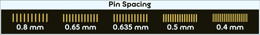 Visual reference of the most common pin spacings. Lets you find out the spacing of an integrated circuit by aligning the pins with the pads. Pin spacing is indicated in millimeters.
 Quick conversion reference between thousandths of an inch (mils or thou) and millimeters.
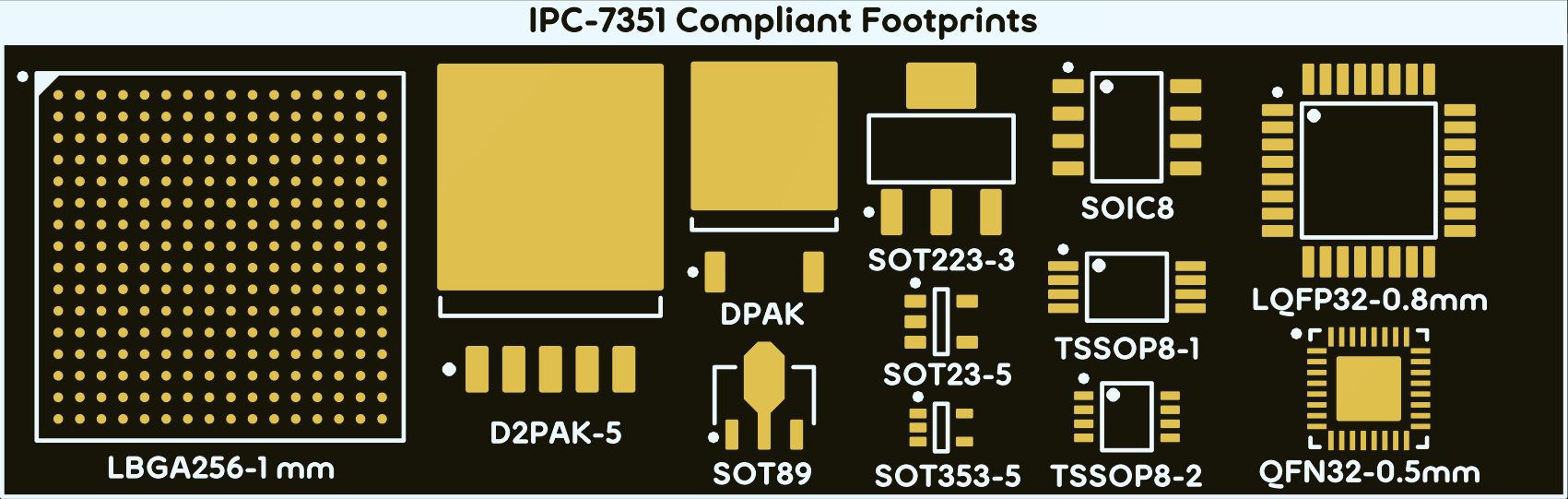 Footprints shown have been chosen by the designer, although attempts have been made to include most common ones. The shorter or smaller versions of the ICs are usually displayed, as the larger versions are symmetric in one or two axes (for example, an SO16 package is like two SO8 in line)
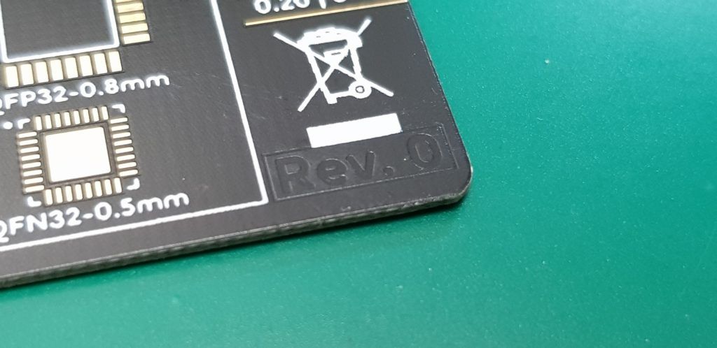 Indicates the version number of the PCB. It has been placed on the bottom copper layer below the solder mask so that it is relatively hidden.
Front
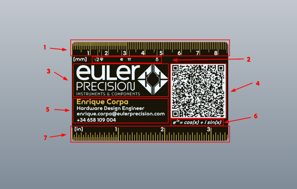
The front of the card contains the typical information found in your standard business card. However, it is easy to see that this is not your regular business card. At first glance, the golden rules at the edges, the Euler Precision logo and the QR code stand out. As part of the card design, some mathematical details have been included (We have Euler in our name, so obviously we had to do it). The card is designed not only to contain our contact info and make ourselves known, but also to be useful to the user, so the receiver wants to keep it. The elements that can be found on the front are:
[1] Millimeter Ruler
The ruler starts from the edge of the card, so it can be used to measure object’s dimensions by resting it on a surface next to that item. The first three centimeters have extra 0.5 mm divisions to increase the available resolution. The rest of the ruler’s divisions are 1 centimeter and 1 mm with a slightly longer mark to indicate half’s of a centimeter.
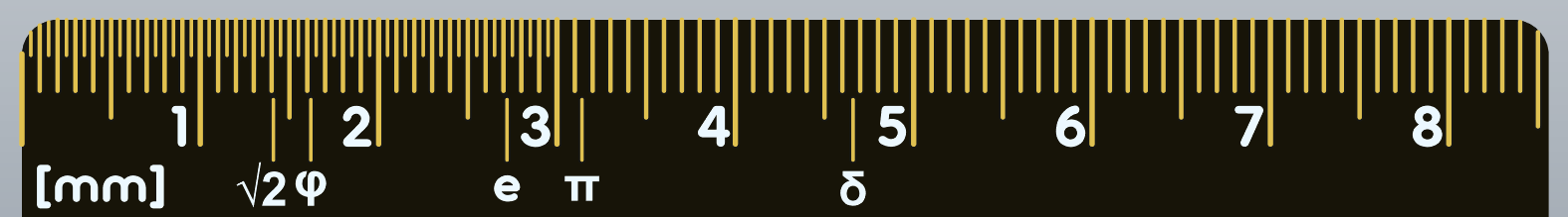
[2] Some fundamental constants
The millimeter ruler has also been used as a real number line to indicate some interesting math constants:- Square root of two: 1.4142… The length of the diagonal of a square with the length of the side equal to 1… someone actually died because of this number…
- Golden ratio: 1.6108… the ratio between two consecutive numbers in the Fibonacci sequence approximates this number. Objects built following this ratio are usually aesthetically pleasing.
- Euler’s number: 2.7182… the only number that when used as a base of the function bx, makes its derivative be itself. This property makes the exponential a frequent solution of many differential equations and therefore appears frequently as the solution of many physical systems.
- The number Pi : 3.1415… is the ratio between the perimeter and the diameter of a circle. Mathematicians’ favorite number.
- Feigenbaum’s constant: 4.6692… is the geometric ratio between the different forks in a bifurcation diagram. It has a close relationship with chaos and the Mandelbrot set.
[3] Euler Precision Logo
[4] VCard QR
The QR code allows contact information to be added to any smartphone quickly and efficiently. Contains contact information in VCard 4 format. Information included in the card is:
- Contact name
- Position
- Company
- Email address
- Company’s web page
- Phone number
[5] Contact information
Although contact information is available in QR form, it has been included in the silkscreen for aesthetics and redundancy reasons.[6]Euler’s formula
Another math reference: Euler’s formula, which relates the complex exponential with rotations in the complex plane.
[7] Imperial Ruler
Just like the millimeter ruler, the ruler starts from the edge and has 25-thou marks (0.635 mm) along the first inch. From there, subsequent marks are one inch (1000 thou, 25.4 mm) and 100 thou (2.54 mm) with short marks to indicate 50 thousand (1.27 mm).
Back:
 The back of the card has some engineering references for the design of printed circuit boards. All component tables and footprints follow the IPC recommendations, and the specific standards for each table are shown below.
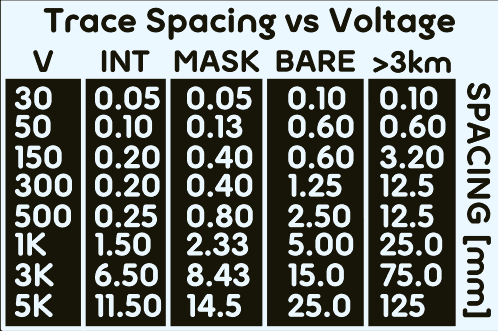
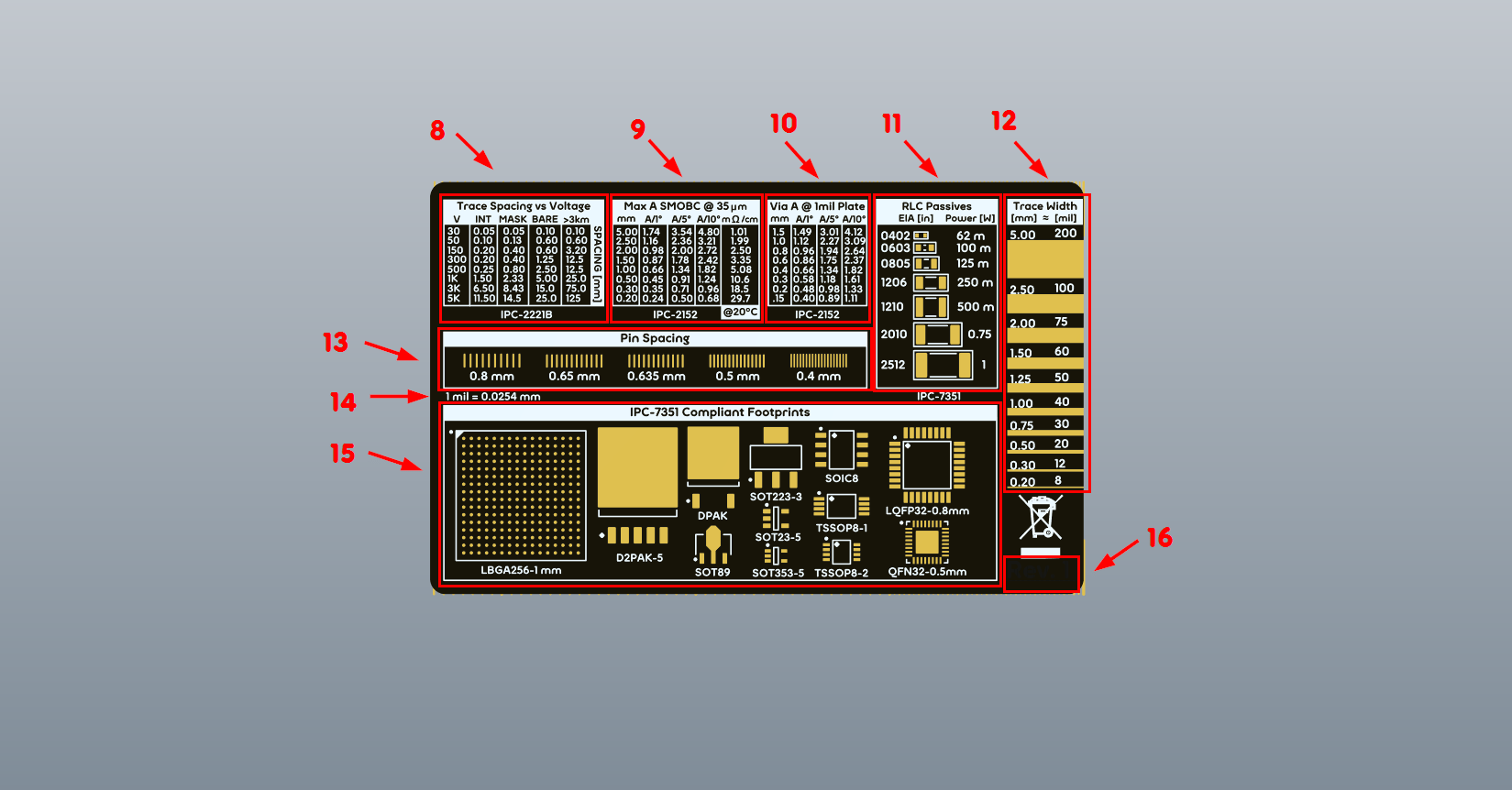
[8] Trace clearance vs voltage
This table shows the required spacing (clearance) according to the IPC-2222A table. The voltage at which an electric arc (corona) occurs between two conductors is determined, according to Paschen’s law, by the distance between them, the atmospheric pressure and the composition of the gas that surrounds them. The values in the IPC table are very conservative with respect to the usual dielectric breakdown of air, but it is highly recommended to follow them. As a side note, clearance is not the same as creepage.
[9] Trace current carrying capacity vs width
Maximum current for a single copper trace covered with solder mask (SMOBC: Solder Mask Over Bare Copper) as a function of width and allowed temperature rise (ΔT).
Most trace widths in the table match the trace samples shown in [12].
[10] Via current carrying capacity vs diameter
Maximum current through a via as a function of its diameter and the allowed temperature rise(ΔT). A two-layer, 0.00254 mm (1 mil) metallized via is assumed. Values shown in the table are for the most common via diameters.
[11] Passive (RLC) SMD package table
Samples of the most common SMD package sizes for passive components, indicating their size in imperial units with the EIA standard, since this is the most common nomenclature. Footprints follow IPC recommendations.
A maximum recommended power rating is also indicated in the case of resistors of these sizes, taking as reference the Vishay’s D/CRCW series (Standard Thick Film Chip Resistors).
Capacitors and inductors ideally don’t dissipate power, but each case needs to be studied individually since stray resistance in them can produce significant dissipation.
[12] Trace size in mm and mils
[13] Common IC pin spacing
Visual reference of the most common pin spacings. Lets you find out the spacing of an integrated circuit by aligning the pins with the pads. Pin spacing is indicated in millimeters.
[14] Quick conversion remainder
[15] Footprints
Footprints shown have been chosen by the designer, although attempts have been made to include most common ones. The shorter or smaller versions of the ICs are usually displayed, as the larger versions are symmetric in one or two axes (for example, an SO16 package is like two SO8 in line)
[16] Revision mark
Indicates the version number of the PCB. It has been placed on the bottom copper layer below the solder mask so that it is relatively hidden.
PCB change log:
Rev 0: manufactured by JLCPCB
- Initial version
Rev 1: manufactured by PCBWay
- Fixed an styling inconsistency in [12] numbers for mm and mils.
- Improved TSSOP8-1 solder mask expansion.